Resistance Of A System Of Resistors
Key Notes:
Definition of Resistance:
- Resistance is a measure of how much a resistor opposes the flow of electric current. It is denoted by the symbol R and measured in ohms (Ω).

Ohm’s Law:
- The relationship between voltage (V), current (I), and resistance (R) is given by Ohm’s Law:
V = IR
- This law helps calculate the resistance when the voltage and current in the circuit are known.

Series Combination of Resistors:
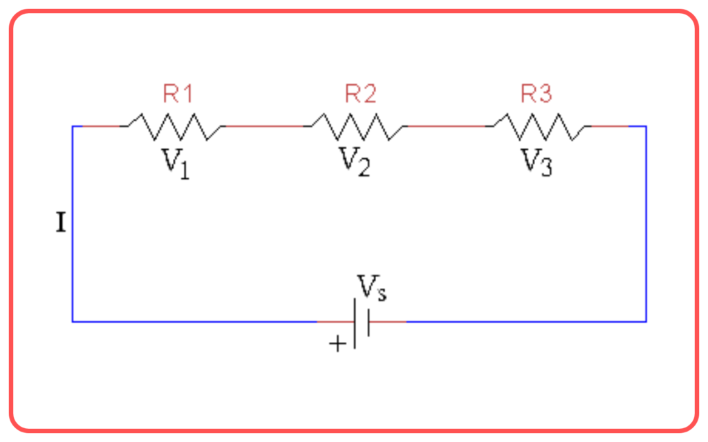
- When resistors are connected end-to-end, they are said to be in series.
- The total or equivalent resistance (Req) of resistors in series is the sum of the individual resistances:
Req = R1 + R2 + R3 + …
- The current through each resistor is the same, but the voltage across each resistor is different.

Parallel Combination of Resistors:
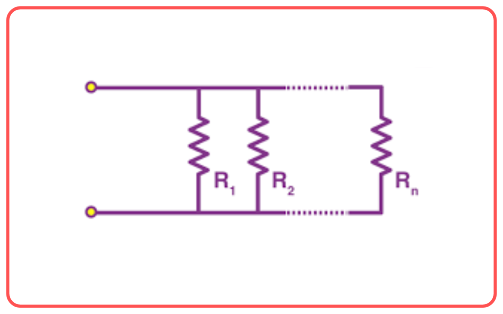
- When resistors are connected such that they share the same two nodes, they are in parallel.
- The reciprocal of the total or equivalent resistance (Req) for resistors in parallel is the sum of the reciprocals of the individual resistances:
1/Req = 1/R1 + 1/R2 + 1/R3 + …
- The voltage across each resistor is the same, but the current through each resistor is different.

Combination of Series and Parallel Resistors:
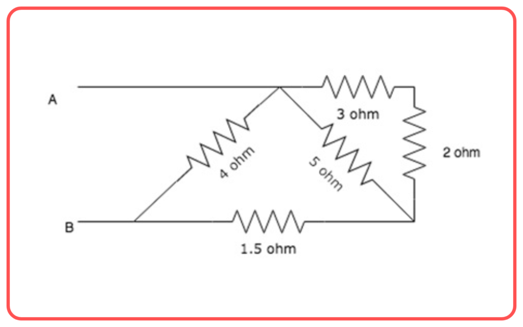
- In practical circuits, resistors can be arranged in combinations of series and parallel.

- To calculate the total resistance, first simplify the parallel and series parts step-by-step, reducing the circuit to an equivalent resistance.
Resistances in Everyday Applications:
- Resistors are used in electronic devices to control the current and voltage levels, ensuring safe operation of components like LEDs and transistors.
Factors Affecting Resistance:
Resistance of a conductor depends on:

- Material: Different materials have different resistivity.
- Length: Resistance is directly proportional to the length of the conductor.
- Cross-sectional Area: Resistance is inversely proportional to the cross-sectional area.
- Temperature: Resistance usually increases with an increase in temperature.
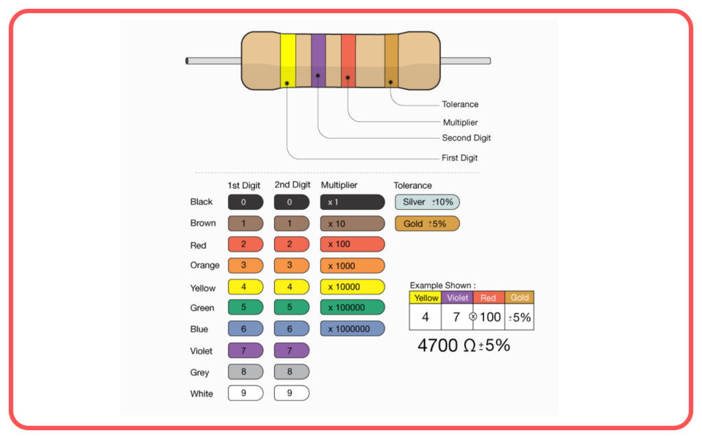
Resistor Color Code:
- Resistors are labeled with a color code to indicate their resistance value. Understanding how to read this code is important for identifying resistances in circuits.

Let’s practice!

