Circuit Diagram
Key Notes:
Definition:
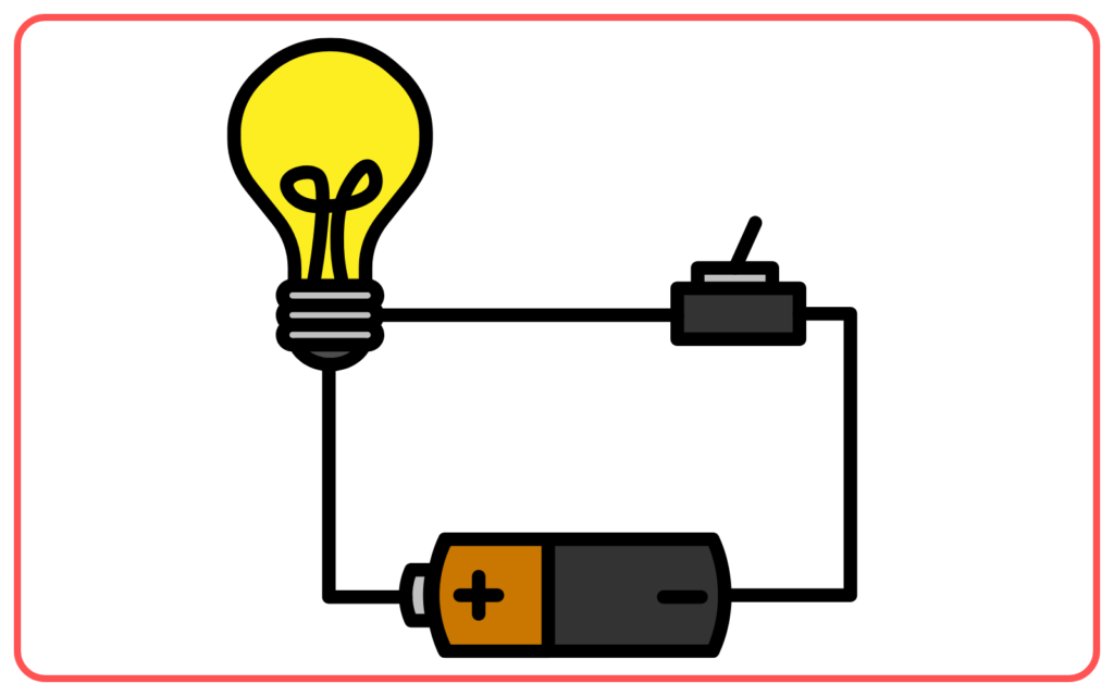
- A circuit diagram is a simplified graphical representation of an electrical circuit. It shows the arrangement of various components like resistors, switches, batteries, and wires using standardized symbols.

Importance:
- Circuit diagrams provide a clear way to understand and analyze the behavior of an electric circuit without physically building it.
Standard Symbols:
- Battery: Represented by a series of short and long parallel lines.

- Resistor: Drawn as a zigzag line.

- Switch: Represented by a break in a line with a small open or closed segment.

- Wires: Represented by straight lines connecting the components.

- Bulb: Represented by a circle with a cross inside it.

Types of Circuits:

- Series Circuit: All components are connected end-to-end, providing a single path for the current to flow.
- Parallel Circuit: Components are connected across common points, providing multiple paths for the current to flow.
How to Read a Circuit Diagram:
- Identify the symbols and their arrangement.
- Follow the path of current flow starting from the positive terminal of the battery.
- Check how components are connected (series or parallel).
Ohm’s Law in Circuit Diagrams:
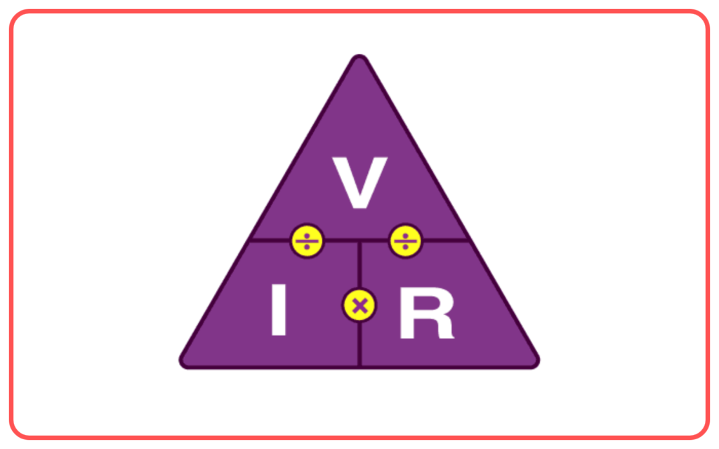
- Ohm’s law (V = IR) can be applied to circuit diagrams to calculate the voltage, current, or resistance at various points in the circuit.

Applications:
- Circuit diagrams are used in electronics, engineering, and physics to plan, design, and troubleshoot electrical circuits.
Drawing a Circuit Diagram:
- Start by placing the power source (battery).
- Add components like resistors, bulbs, and switches in the desired configuration (series or parallel).
- Use straight lines for wires and connect all components according to the desired circuit design.
Let’s practice!

